ESP32用のArdupilotを書き込む
前回はESP32用のArdupilotをビルドしてみました。ビルドしたら実際にESP32へ書き込んでみましょう。
ESP32への書き込みはArdupilotだからといって特別な方法が必要なわけではなく,ArduinoIDEから書き込むときと同様にFTDIのUSBシリアル変換器のTX, RXとESP32のTX, RX(GPIO3とGPIO1)を接続して,ESP32のGPIO0をGNDに落としたまま起動すると書き込みモードに入るというおなじみの方法です。
前回と同様にDocker環境で作業します。
sdkconfigの修正
基本的にコマンド1つで書き込み可能ですが,ファームウェアの作成時にエラーが出るのでlibraries/AP_HAL_ESP32/targets/esp-idf/sdkconfigを以下のように修正します。
CONFIG_PARTITION_TABLE_OFFSET=0x10000
コンテナの起動と書き込み
ビルドするときに作成したardupilot:esp32イメージを起動しますが,/dev/ttyUSB0などのシリアルデバイスが使えるように特権モードを与えて,/devもマウントします。
$ docker run --rm -it --privileged --name='ardupilot' -v `pwd`:/ardupilot -v /dev:/dev ardupilot:esp32 bash
コンテナを起動したら以下のコマンドを実行してESP32へ書き込みます。ESPPORTの指定は環境に合わせて変更してください。
$ . ./modules/esp_idf/export.sh
$ python -m pip install empy pexpect
$ ESPBAUD=921600 ESPPORT=/dev/ttyUSB0 ./waf copter --upload
簡単ですね。
ビルドのときのオプションに--uploadがついているだけなので,上記のコマンドだけでビルドから書き込みまでやってくれます。
ESP32用のArdupilotをビルドする
Arudupilotを見ていたらどうやらESP32上でも動かせそうです。 ESP32-CAMなんかをフライトコントローラにしたら,100g未満でウェイポイント飛行しながら空撮できる固定翼ドローンができるんじゃないでしょうか? まずはArdupilotをESP32向けにビルドしてみます。
環境
- Ubuntu 20.04
- Docker version 20.10.14, build a224086349
ソースのクローン
以下のコマンドでソースをクローンしてきます。
$ git clone https://github.com/ArduPilot/ardupilot.git
$ cd ardupilot
$ git submodule --init --recursive
ビルド環境コンテナイメージの作成
用意されているDockerfileを使います。以下のページにビルド手順が書いてあります。
Dockerfileがあるディレクトリで以下を実行します。
$ docker build . -t ardupilot
ardupilotディレクトリをマウントしてコンテナを起動します。
$ docker run --rm -it -name="ardupilot" -v `pwd`:/ardupilot ardupilot:latest bash
ESP32用ビルド環境の追加
ESP32向けのビルド方法は以下に書いてあります。
コンテナ内で以下のコマンドを実行します。
$ sudo apt update
$ sudo apt-get install git wget flex bison gperf python-setuptools cmake ninja-build ccache libffi-dev libssl-dev dfu-util
$ sudo apt-get install python3 python3-pip python3-setuptools
$ sudo update-alternatives --install /usr/bin/python python /usr/bin/python3 10
後のビルドステップでエラーが出るので以下のコマンドを実行してlibusb,empy, pexpectをインストールしておきます。
$ sudo apt install -y libusb-1.0-0
$ python -m pip install empy pexpect
以下のコマンドでESP32のビルドツールをインストールします。
$ ./Tools/scripts/esp32_get_idf.sh
$ cd modules/esp_idf
$ ./install.sh
$ . ./export.sh
別のターミナルを開いてdocker commitしておきます。
$ docker commit ardupilot ardupilot:esp32
ソースの修正
あとは./waf configureしたあと./wafでビルドするだけですが,以下2つのissueを参考にソースを修正しておきます。
以下に修正手順を示しますが,修正済みのソースを置きましたので,以下をクローンしてもOKです。
Tools/ardupilotwaf/board.py
Tools/ardupilotwaf/boards.pyの119行目付近を以下のように修正します。
# allow enable of custom controller for any board
# enabled on sitl by default
# if (cfg.options.enable_custom_controller or self.get_name() == "sitl") and not cfg.options.no_gcs:
#     env.ENABLE_CUSTOM_CONTROLLER = True
#     env.DEFINES.update(
#         AP_CUSTOMCONTROL_ENABLED=1,
#     )
#     env.AP_LIBRARIES += [
#         'AC_CustomControl'
#     ]
#     cfg.msg("Enabled custom controller", 'yes')
# else:
env.DEFINES.update(
    AP_CUSTOMCONTROL_ENABLED=0,
)
cfg.msg("Enabled custom controller", 'no', color='YELLOW')
GCS_FTPのエラー
libraries/AP_Filesystem/AP_Filesystem.hの35行目〜37行目をlibraries/GCS_MAVLink/GCS_FTP.cppにコピーします。
ビルド
上記の修正を行ったら,以下のコマンドでビルドします。
$ cd /ardupilot
$ . ./modules/esp_idf/export.sh
$ ./waf configure
$ ./waf configure --board=esp32diy
$ python -m pip install empy
$ python -m pip install pexpect
$ ./waf copter
以上でとりあえずエラーを回避してビルドできました。issueが立っているのでそのうちこういう小手先の修正をしなくてもビルドできるようになるでしょう。(人任せ)
ROS1 Noetic とROS2 FoxyでUUV Simulatorを使う

UUV SimulatorはUUV(Unmanned Underwater Vehicle)のためのGazebo
パッケージです。GitHubのmasterブランチは2020年に更新が止まっており,noeticに対応していませんが,このissueによるとnoeticに対応したソースを作ってくれている人がいます。
また,UUV SImulatorはROS1パッケージであり,UUVの舵やスラスタを動作させるトピック名もROS1仕様ですが,トピック名を変換するノードを記述してROS2と連携させてみます。
環境
- ROS noetic
- ROS2 foxy
- Gazebo 11.1
ROSとROS2のインストール
以下の手順でnoeticとfoxyをインストールしておきます。
また,あとの行程でros1_bridgeを使うのでインストールしておきます。
$ sudo apt install ros-foxy-ros1-bridge
UUV Simulatorのクローンとビルド
以下のコマンドでUUV Simulatorのクローンとソースビルドを行います。UUV SImulatorだけではただ海の環境がGazeboに表示されるだけなのでLAUVやECA_A9といったUUVのモデルもインストールしておきます。
aptでインストールしたROSパッケージと同様に起動できるようにするため,-DCMAKE_INSTALL_PREFIX=/opt/ros/noeticをつけてcatkin_makeしています。
$ mkdir -p ~/uuv_sim_ws/src
$ cd ~/uuv_sim_ws/src
$ git clone -b noetic https://github.com/arturmiller/uuv_simulator.git
$ git clone https://github.com/uuvsimulator/rexrov2.git
$ git clone https://github.com/uuvsimulator/lauv_gazebo.git
$ git clone https://github.com/uuvsimulator/eca_a9.git
$ git clone https://github.com/uuvsimulator/desistek_saga.git
$ source /opt/ros/noetic/setup.bash
$ cd ~/uuv_sim_ws
$ catkin_make
$ sudo -s
# source /opt/ros/noetic/setup.bash
# catkin_make -DCMAKE_INSTALL_PREFIX=/opt/ros/noetic install
動作確認
コンソールを3つ開き,以下のコマンドを入力していきます。
1つ目のコンソールで以下を実行するとGazeboが起動し,海の環境がロードされます。
$ source /opt/ros/noetic/setup.bash
$ roslaunch uuv_gazebo_worlds ocean_waves.launch
2つ目のコンソールで以下のコマンドを実行し,lauvのモデルをロードします。
$ source /opt/ros/noetic/setup.bash
$ roslaunch lauv_description upload.launch mode:=default x:=0 y:=0 z:=-20
3つ目のコンソールで以下のコマンドを実行し,lauvを前進させます。
$ source /opt/ros/noetic/setup.bash
$ rostopic pub /lauv/thrusters/0/input uuv_gazebo_ros_plugins_msgs/FloatStamped '{header: {stamp: now}, data: -100}'
ROS2からUUV Simulatorを使う
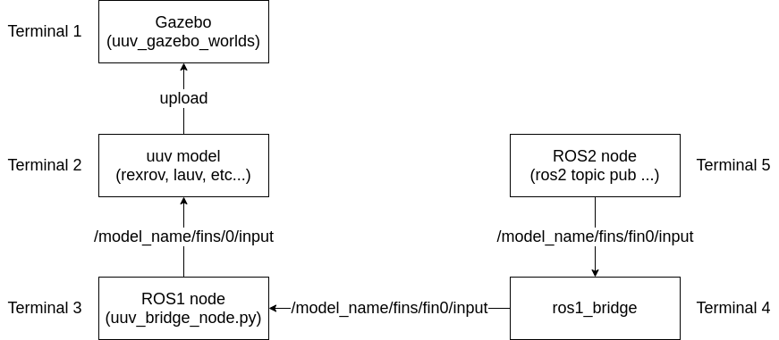
上記の動作確認で,/lauv/thrusters/0/inputトピックにPublishしてスラスタを回転させていましたが,ROS2ではこのように途中に0だけの名前が入ったトピック名は許容されません。このため単純にros1_bridgeを実行しただけではROS2でUUV Simulatorを使うことができません。
そこで/lauv/thrusters/thruster0/inputをSubし,/lauv/thrusters/0/inputへPubするROS1ノードを作成し,ROS2からUUV Simulatorを使えるようにします。
全体構成は以下のようになります。
トピックの変換ノードは以下のリポジトリで公開しています。
次からはノードを作成する作業手順です。
パッケージの作成
以下のコマンドを実行し,uuv_bridgeという名前でROSパッケージを作成します。
$ source /opt/ros/melodic/setup.bash
$ cd ~/catkin_ws/src
$ catkin_create_pkg uuv_bridge rospy gazebo
CMakeLists.txtの編集
以下のように159行目付近のコメントアウトをもとに戻し,my_python_scriptをbridge.pyに置き換えます。
## Mark executable scripts (Python etc.) for installation
## in contrast to setup.py, you can choose the destination
 catkin_install_python(PROGRAMS
   scripts/bridge.py
   DESTINATION ${CATKIN_PACKAGE_BIN_DESTINATION}
 )
ソースの記述
- /lauv/fins/0/input〜/lauv/fins/3/input
- /lauv/thrusters/0/input
へPublishするようなノードを作成します。
以下のソースをuuv_bridge_node.pyとしてscriptsディレクトリに保存します。
また,uuv_bridge_node.pyにはsudo chmod +x uuv_bridge_node.pyで実行権限を付加しておきます。
#!/usr/bin/env python
# -*- coding: utf-8 -*-
import rospy
from std_msgs.msg import Float64
from uuv_gazebo_ros_plugins_msgs.msg import FloatStamped

# Subscriber用のコールバックを生成するクロージャー
def actuator_callback(inTopic, publisher):
    pub = publisher

    def callback(data):
        # rospy.loginfo(rospy.get_caller_id() + " I heard %f", data.data)

        pubdata = FloatStamped()
        pubdata.header.stamp = rospy.Time.now()
        pubdata.data = data.data

        pub.publish(pubdata)
    return callback

def converter(list):
    rospy.init_node('rosbridge_node', anonymous=True)

    # 変換リストからPublisher,SubScriberを設定
    for item in list:
        callback = actuator_callback(item[0], rospy.Publisher(item[1], FloatStamped, queue_size=10))
        rospy.Subscriber(item[0], Float64, callback)

    rospy.spin()

if __name__ == '__main__':
    convert_list = [
        # 変換元をSubscribeし,データをそのまま変換先へPublishする
        # 変換元,            変換先
        ('/lauv/fins/fin0/input', '/lauv/fins/0/input'),
        ('/lauv/fins/fin1/input', '/lauv/fins/1/input'),
        ('/lauv/fins/fin2/input', '/lauv/fins/2/input'),
        ('/lauv/fins/fin3/input', '/lauv/fins/3/input'),
        ('/lauv/thrusters/thruster0/input', '/lauv/thrusters/0/input'),
    ]
    converter(convert_list)
ビルド,インストール
以下のコマンドを実行してビルドします。
$ cd ~/catkin_ws
$ catkin_make
以下のコマンドでインストールします。
$ sudo -s
# source /opt/ros/noetic/setup.bash
# catkin_make -DCMAKE_INSTALL_PREFIX=/opt/ros/noetic install
動作確認
コンソールを5つ開き,以下のコマンドを入力していきます。
1つ目のコンソールで以下を実行するとGazeboが起動し,海の環境がロードされます。
$ source /opt/ros/noetic/setup.bash
$ roslaunch uuv_gazebo_worlds ocean_waves.launch
2つ目のコンソールで以下のコマンドを実行し,lauvのモデルをロードします。
$ source /opt/ros/noetic/setup.bash
$ roslaunch lauv_description upload.launch mode:=default x:=0 y:=0 z:=-20
3つ目のコンソールで以下のコマンドを実行し,先程作成したuuv_bridgeを起動します。
$ source /opt/ros/noetic/setup.bash
$ rosrun uuv_bridge uuv_bridge_node.py
4つ目のコンソールで以下のコマンドを実行し,ros1_bridgeを起動します。
$ source /opt/ros/foxy/setup.bash
$ ros2 run ros1_bridge dynamic_bridge
5つ目のコンソールで以下のコマンドを実行し,lauvのアクチュエータへ指令値をPubします。
$ source /opt/ros/foxy/setup.bash
$ ros2 topic pub /lauv/fins/fins0/input std_msgs/Float64 '{data: 0.5}'
また,以下のようにすることでlauvのセンサ値をROS2側で取得できます。
$ ros2 topic echo /lauv/gps
以上にROS2 FoxyからUUV Simulatorを使うことができました。
ESP32CAMをMicro XRCE-DDSでROS2ノード化する

https://micro-xrce-dds.docs.eprosima.com/en/latest/
Micro XRCE-DDSはマイコンでも動作する軽量なクライアントライブラリで利用できるDDSとのインターフェースです。マイコンはMicro XRCE-DDS Agentと通信し,Micro XRCE-DDS AgentはマイコンとのやりとりをROS2が利用するDDSへ転送します。
この記事ではDocker for WindowsでMicro XRCE-DDS Agentを実行し,ESP32側ではros2arduinoをMicro XRCE-DDS Client として利用します。
環境
ホスト
マイコン
- ESP32-CAM
- ros2arduino 0.2.1
ファイアウォールの設定
以下の説明ではMicro XRCE-DDS AgentはUDPの2018ポートを使用します。Windows ファイアウォールの設定を変更し,docker backendへのUDPでのアクセスを許可しておきます。

Micro XRCE-DDS Agentの準備
Micro XRCE-DDS Agentはdockerで動作させます。以下のDockerfileを作成します。
# docker build -t ros2:dashing .
FROM ubuntu:18.04
ENV DEBIAN_FRONTEND noninteractive

ENV ROS_DISTRO dashing

# ロケールのセットアップ
RUN apt-get update && apt-get install -y locales && \
    dpkg-reconfigure locales && \
    locale-gen ja_JP ja_JP.UTF-8 && \
    update-locale LC_ALL=ja_JP.UTF-8 LANG=ja_JP.UTF-8
ENV LC_ALL   ja_JP.UTF-8
ENV LANG     ja_JP.UTF-8
ENV LANGUAGE ja_JP.UTF-8

# APTソースリストの設定
RUN apt-get update && \
    apt-get install -y curl gnupg2 lsb-release && \
    curl http://repo.ros2.org/repos.key | apt-key add - && \
    sh -c 'echo "deb [arch=amd64,arm64] http://packages.ros.org/ros2/ubuntu \
    `lsb_release -cs` main" > /etc/apt/sources.list.d/ros2-latest.list' && \
    apt-get update

# ROS2パッケージのインストール
RUN export ROS_DISTRO=dashing && \
    apt-get install -y ros-$ROS_DISTRO-desktop \
    python3-colcon-common-extensions python3-rosdep python3-argcomplete && \
    rosdep init && \
    rosdep update

## 環境設定
RUN    echo "source /opt/ros/$ROS_DISTRO/setup.bash" >> ~/.bashrc

## Micro XRCE-DDS Agentのビルド
## https://github.com/ROBOTIS-GIT/ros2arduino
RUN apt-get install -y git
WORKDIR work
SHELL ["/bin/bash", "-c"]
RUN git clone https://github.com/eProsima/Micro-XRCE-DDS-Agent.git && \
    cd Micro-XRCE-DDS-Agent && \
    git checkout -b v1.3.0 refs/tags/v1.3.0 && \
    mkdir build && cd build && \
    source /opt/ros/dashing/setup.bash && \
    cmake .. && \
    make && \
    make install && \
    ldconfig /usr/local/lib/
Dockerfileを作成したら以下のコマンドでビルドします。
> docker build -t micro-xrce-dds-agent:v1.3.0 .
ビルドしたら以下コマンドで起動します。
> docker run --rm -it -p 192.168.0.10:2018:2018 -p 192.168.0.10:2018:2018/udp micro-xrce-dds-agent:v1.3.0
# cd MicroXRCEAgent/build
# ./MicroXRCEAgent udp4 -p 2018
起動すると以下のようなメッセージが表示されます。
root@docker-desktop:/work/Micro-XRCE-DDS-Agent/build# ./MicroXRCEAgent udp4 -p 2018
Press CTRL+C to exit
[1612241367.034260] info     | UDPv4AgentLinux.cpp | init                     | running...             | port: 2018
ESP32CAM側プログラム
あらかじめArduino IDEでros2arduinoライブラリをインストールしておきます。

Arduino IDEで以下のプログラムを作成し,ESP32へ転送します。#define AGENT_IPにはMicro XRCE-DDS Agentを動作させているホストのIPアドレスを指定します。
#include <ros2arduino.h>

#include <WiFi.h>
#include <WiFiUdp.h>
#define SSID       "ssid"
#define SSID_PW    "password"
#define AGENT_IP   "ipaddress ex.192.168.0.10"
#define AGENT_PORT 2018 //AGENT port number

#define PUBLISH_FREQUENCY 1 //hz

#define LED_BUILTIN 4

void publishString(std_msgs::String* msg, void* arg)
{
  (void)(arg);

  static int cnt = 0;
  sprintf(msg->data, "Hello ros2arduino %d", cnt++);
}

void subscribeLed(std_msgs::Bool* msg, void* arg)
{
  (void)(arg);

  digitalWrite(LED_BUILTIN, msg->data);
}

class StringPub : public ros2::Node
{
public:
  StringPub()
  : Node("ros2arduino_pub_node")
  {
    ros2::Publisher<std_msgs::String>* publisher_ = this->createPublisher<std_msgs::String>("arduino_chatter");
    this->createWallFreq(PUBLISH_FREQUENCY, (ros2::CallbackFunc)publishString, nullptr, publisher_);

    this->createSubscriber<std_msgs::Bool>("arduino_led", (ros2::CallbackFunc)subscribeLed, nullptr);
  }
};

WiFiUDP udp;

void setup()
{
  Serial.begin(115200);
  Serial.setDebugOutput(true);
  Serial.println();

  pinMode(LED_BUILTIN, OUTPUT);

  WiFi.begin(SSID, SSID_PW);
  while(WiFi.status() != WL_CONNECTED) {
    delay(500);
    Serial.print(".");
  }
  Serial.println("");
  Serial.print("WiFi Connected. IP address : ");
  Serial.println(WiFi.localIP());

  ros2::init(&udp, AGENT_IP, AGENT_PORT);
  Serial.println("Setup completed.");
}

void loop()
{
  static StringPub StringNode;

  ros2::spin(&StringNode);
}
ESP32CAMとMicro XRCE-DDS Agentの接続
上記のプログラムを書き込んだESP32CAMを起動すると,Micro XRCE-DDS AgentにESP32CAMが接続され以下のようなメッセージが表示されます。
root@83535a5f72b3:/work/Micro-XRCE-DDS-Agent/build# ./MicroXRCEAgent udp4 -p 2018
Press CTRL+C to exit
[1612242146.336194] info     | UDPv4AgentLinux.cpp | init                     | running...             | port: 2018
[1612242160.276226] info     | Root.cpp           | create_client            | create                 | client_key: 0xAABBCCDD, session_id: 0x81
[1612242160.279092] info     | SessionManager.hpp | establish_session        | session established    | client_key: 0x2864434397, address: 172.17.0.1:8331
[1612242160.281801] info     | SessionManager.hpp | establish_session        | session re-established | client_key: 0x2864434397, address: 172.17.0.1:8331
[1612242160.281854] info     | SessionManager.hpp | establish_session        | session re-established | client_key: 0x2864434397, address: 172.17.0.1:8331
[1612242160.281866] info     | SessionManager.hpp | establish_session        | session re-established | client_key: 0x2864434397, address: 172.17.0.1:8331
[1612242160.281873] info     | SessionManager.hpp | establish_session        | session re-established | client_key: 0x2864434397, address: 172.17.0.1:8331
[1612242160.281880] info     | SessionManager.hpp | establish_session        | session re-established | client_key: 0x2864434397, address: 172.17.0.1:8331
[1612242160.281887] info     | SessionManager.hpp | establish_session        | session re-established | client_key: 0x2864434397, address: 172.17.0.1:8331
ROS2との接続
Micro XRCE-DDS Agentを起動するために作成したDockerイメージにはROS2 Dashingの環境も含まれています。以下のようにしてros2 topic listを実行し,arduino_chatterとarduino_ledが表示されることを確認します。
> docker run --rm -it --net host micro-xrce-dds-agent:v1.3.0
# ros2 topic list
/arduino_chatter
/arduino_led
/parameter_events
/rosout
ros2 topic echo arduino_chatterを実行すると以下のようにESP32CAMからPublishされたメッセージが表示されます。
root@docker-desktop:/work# ros2 topic echo arduino_chatter
data: Hello ros2arduino 257
---
data: Hello ros2arduino 258
---
data: Hello ros2arduino 259
---
data: Hello ros2arduino 260
---
data: Hello ros2arduino 261
---
data: Hello ros2arduino 262
---
data: Hello ros2arduino 263
---
また,ros2 topic pub arduino_led std_msgs/msg/Bool '{data: true}'を実行するとESP32CAM上に実装されているLEDが点灯します。ros2 topic pub arduino_led std_msgs/msg/Bool '{data: false}'を実行すると消灯します。
root@docker-desktop:/work# ros2 topic pub arduino_led std_msgs/msg/Bool '{data: true}'
publisher: beginning loop
publishing #1: std_msgs.msg.Bool(data=True)

publishing #2: std_msgs.msg.Bool(data=True)

Raspberry Pi 4 + Ubuntu 20.04 + ROS2 foxyでルンバを動かす
ラズパイでルンバを動かす話はググるとたくさん出てきますが,ラズパイ上でROS2ノードをビルドしようとすると途中で止まったりやたらと時間がかかったりとハマりどころが多かったので以下にまとめます。
手順
以下の手順で進めます。
- ソースのダウンロード
- qemu-user-staticでビルド
- Raspberry Pi 4に転送する
- 動作確認
ルンバ用ROS2ノードのダウンロード
以下のソースをcreate_ws/srcにダウンロードします。
$ mkdir -p create_ws/src
$ cd create_ws/src
$ git clone -b foxy https://github.com/AutonomyLab/create_robot.git
$ git clone https://github.com/AutonomyLab/libcreate.git
qemu-user-staticを使ったDockerコンテナでビルドする
前回の記事で作成したRaspberry Pi 用 Ubuntu 20.04をx86 PC上で動かすコンテナを起動し,その中でビルドします。
まずは先ほどダウンロードしたソースがあるcreate_wsをマウントしてコンテナを起動します。
$ docker run -it -v $(pwd)/create_ws:/home/ubuntu/create_ws --name raspi raspi-ubuntu-ros2:foxy /bin/bash
# adduser ubuntu
# usermod -a -G sudo ubuntu
# chmod ubuntu:ubuntu /home/ubuntu
# su ubuntu
$ cd ~/create_ws
libcreateの依存パッケージをインストールします。
$ sudo apt update
$ sudo apt install build-essential cmake libboost-system-dev libboost-thread-dev
create_robotの依存パッケージをインストールします。
$ source /opt/ros/foxy/setup.bash
$ sudo apt install python3-rosdep
$ cd ~/create_ws
$ sudo rosdep init
$ rosdep update
$ rosdep install --from-paths src -i
ビルドします。
$ colcon build
なにかエラーが出ています。
Summary: 6 packages finished [8min 15s]
  1 package had stderr output: libcreate
libcreateのstderr.logを見てみるとtestのビルドに入ったメッセージが出ているだけで特にエラーではないようなのでこのまま続行します。
$ cat log/latest_build/libcreate/stderr.log
GTest installation found. Building tests.
Raspberry Pi 4へ転送
ビルドしたファイルをtarに固めてRaspberry Pi 4へ転送します。
Raspberry Pi 4には予め/home/ubuntu/create_wsディレクトリを作成しておきます。
$ cd ~/create_ws
$ tar cf ../create_ws.tar .
$ cd ..
$ scp create_ws.tar ubuntu@<Raspberry Pi 4のIPアドレス>:~/create_ws
Raspberry Pi 4にSSH接続し,先ほど転送したtarファイルを展開します。
$ ssh ubuntu@<Raspberry Pi 4のIPアドレス>
$ cd create_ws
$ tar xvf create_ws.tar
ros-foxy-xacroをインストール後,動作確認します。
$ sudo apt install ros-foxy-xacro
$ source instal/setup.bash
$ ros2 launch create_bringup create_2.launch
デフォルトでは/dev/ttyUSB0を使ってルンバと通信しようとします。USB - シリアル変換器を接続していないと以下のようなエラーが発生します。
[create_driver-1] what(): open: No such file or directory
ルンバと接続するシリアルポートを変更するには
create_ws/install/create_bringup/share/create_bringup/config/default.yamlのdev:行を変更します。
create_driver:
  ros__parameters:
    # The device path for the robot
    dev: "/dev/ttyAMA2"
...
Raspberry Pi 4で複数のUARTを起動する方法は以下の記事に書いています。
動作確認
ルンバと接続しない状態で起動してみます。
$ ros2 launch create_bringup create_2.launch
...
[create_driver-1] [create::Create] retrying to establish serial connection...
[create_driver-1] [create::Serial] serial error - Operation canceled
[create_driver-1] [create::Serial] failed to receive data from Create. Check if robot is powered!
[create_driver-1] [create::Create] retrying to establish serial connection...
[create_driver-1] [create::Serial] serial error - Operation canceled
...
今度はcreate_driverノードが起動してルンバと接続を試みています。
ルンバと接続
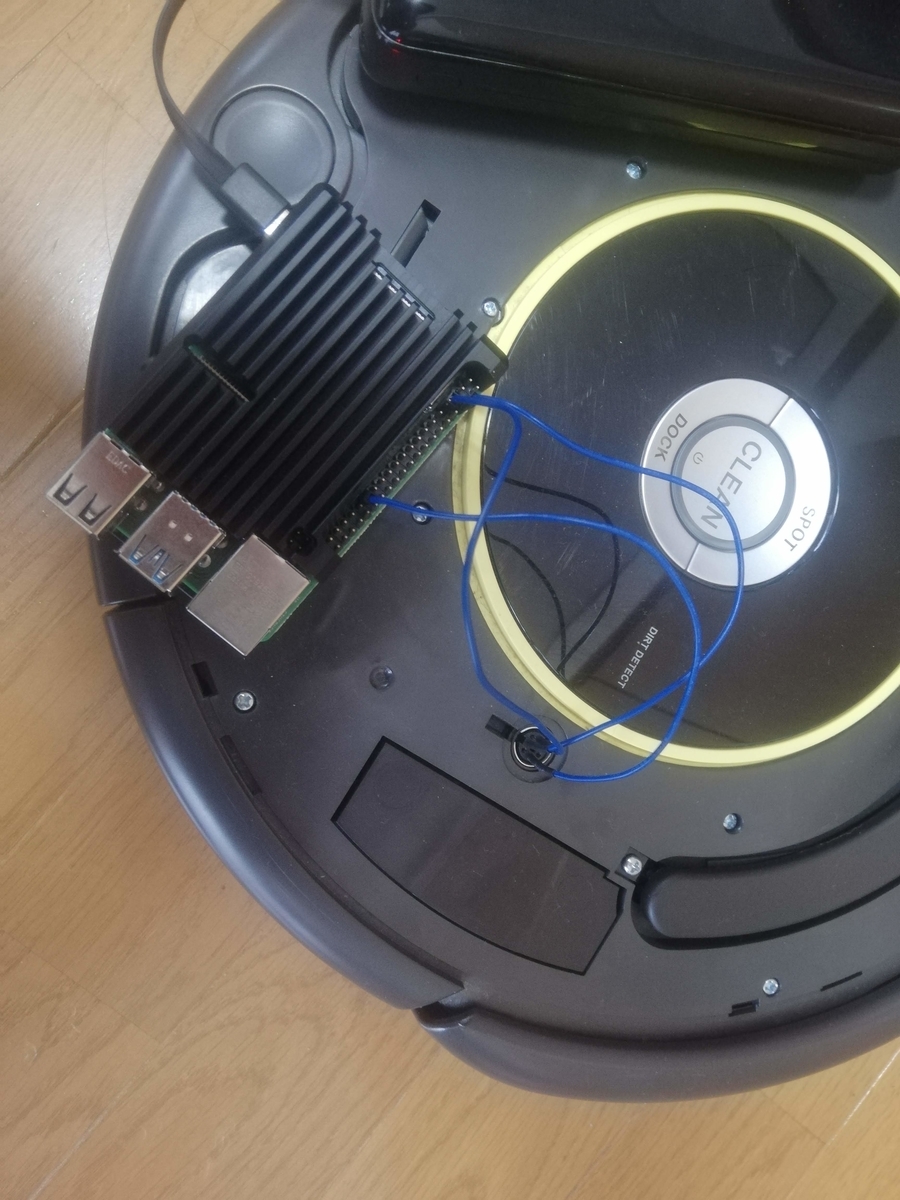
ルンバのシリアルポートとRaspberry Pi 4のUARTを直結してos2 launch create_bringup create_2.launchを実行すると以下のようなメッセージが表示され,ルンバと通信できていることが確認できます。
本当はルンバのシリアルポートとRaspberry Pi 4のUARTは信号レベルが違うのでレベル変換回路を入れる必要がありますが,直結でも動きます。
[create_driver-1] [INFO] [1615607466.306440053] [create_driver]: [CREATE] Connection established.
[create_driver-1] [INFO] [1615607466.306769267] [create_driver]: [CREATE] Battery level 90.95 %
[create_driver-1] [INFO] [1615607466.350583726] [create_driver]: [CREATE] Ready.
ここまで来ればcmd_velにPublishすることでルンバを動かすことができます。
ジョイスティック操作
XBOXのコントローラを使ってルンバを動かしてみます。
XBOXのコントローラをPCに接続したら以下のコマンドでteleop_twist_joyを起動します。
$ ros2 launch teleop_twist_joy teleop-launch.py joy_config:='xbox'
LRボタンを同時押ししながら左スティックを操作するとルンバが動きます。
Raspberry Pi 3 + Ubuntu 20.04 + ROS2 foxy向けクロスコンパイル環境をDockerで構築する
前回の記事では動作確認用のROS2ノードをPythonで書いていましたが,実はrt-net / raspimouse2のソースをRaspberry Pi 3でビルドしようとするとraspimouseパッケージのビルドが25%で止まってしまっていたからでした。
別の環境ならうまく行くかも,ということでRaspberry Pi のROS2で動作するノードをC++で記述してx86 PCでビルドする環境を作ります。
qemu-user-staticでARM用のバイナリをx86命令へ変換しながら実行する仕組みを利用して,Raspberry Pi用のUbunru 20.04イメージをx86 PCで動作させます。その上にROS2をインストールして,あたかもPC上でRaspberry Pi用のROS2が動いているかのように見せかけます。環境はDockerで構築します。
手順
以下の手順でクロスコンパイル環境を構築します。
- DockerでARM用Ubuntu 20.04を動かす
- イメージをtarに固めてdocker importする
- インポートしたDockerイメージをもとにROS2環境を構築する
DockerでARM用Ubuntu 20.04を動かす
Raspberry PiへUbuntu 20.04 LTSをインストールするときに使用したイメージファイルをホストPCでマウントし,qemu-arm-staticを/usr/binへコピーします。
まずはイメージファイルからループバックデバイスを作成します。
$ sudo losetup -fP ubuntu-20.04.2-preinstalled-server-arm64+raspi.img
$ dmesg | grep loop
[    0.113010] Calibrating delay loop (skipped), value calculated using timer frequency.. 5799.77 BogoMIPS (lpj=11599544)
[    0.631321] loop: module loaded
[ 1644.919981] EXT4-fs (loop20): mounted filesystem with ordered data mode. Opts: (null)
[ 2827.012874] EXT4-fs (loop20): mounted filesystem with ordered data mode. Opts: (null)
[14031.188080]  loop20: p1 p2
/dev/loop20に作成されたようです。
$ sudo fdisk -l /dev/loop20
ディスク /dev/loop20: 3.4 GiB, 3259499520 バイト, 6366210 セクタ
単位: セクタ (1 * 512 = 512 バイト)
セクタサイズ (論理 / 物理): 512 バイト / 512 バイト
I/O サイズ (最小 / 推奨): 512 バイト / 512 バイト
ディスクラベルのタイプ: dos
ディスク識別子: 0x4ec8ea53

デバイス      起動 開始位置 最後から  セクタ サイズ Id タイプ
/dev/loop20p1 *        2048   526335  524288   256M  c W95 FAT32 (LBA)
/dev/loop20p2        526336  6366175 5839840   2.8G 83 Linux
loopデバイスが作成されており,ubuntu 20.04のイメージに含まれるLinuxパーティションは/dev/loop20p2になっています。
ローカル環境に余計なものを入れたくないのでDockerコンテナを立ち上げ,適当なところ(ここでは/mnt)にマウントして作業します。
$ docker run --rm -it --privileged -v $(pwd):/home --name ubuntu ubuntu:20.04
# mount /dev/loop20p2 /mnt
作業用のコンテナ内でqemu-user-staticをインストールします。
# apt update
# apt install -y qemu-user-static
qemu-user-staticでインストールされたコンテナ内の/usr/bin/qemu-arm-staticをイメージファイルの/usr/binにコピーします。
# cp /usr/bin/qemu-arm-static /mnt/usr/bin
修正したイメージファイルをtarに固めます。
# cd /mnt
# tar cf /home/raspi-ubuntu-20.04.tar .
コンテナを終了し,作成したtarファイルのオーナーを変更しておきます。
$ sudo chown ユーザー名:ユーザー名 raspi-ubuntu-20.04.tar
tarファイルをDockerにインポートします。
$ docker import raspi-ubuntu-20.04.tar raspi-ubuntu:20.04
インポートしたイメージを起動します。
$ docker run -it --name raspi-ubuntu raspi-ubuntu:20.04 /bin/bash
root@143d831747f9:/# arch
aarch64
アーキテクチャはaarch64になっており,ARM用のUbuntu 20.04イメージが実行されています。
standard_init_linux.go:211: exec user process caused "exec format error"というエラーが出たら以下を実行します。
$ docker run --rm --privileged multiarch/qemu-user-static --reset -p yes
ROS2のインストール
raspi-ubuntu:20.04イメージが作成できたら以下のようなDockerfileを作成してビルドします。
FROM raspi-ubuntu:20.04

RUN apt update && apt install -y curl gnupg2 lsb-release
RUN curl -s https://raw.githubusercontent.com/ros/rosdistro/master/ros.asc | apt-key add -
RUN sh -c 'echo "deb [arch=$(dpkg --print-architecture)] http://packages.ros.org/ros2/ubuntu $(lsb_release -cs) main" > /etc/apt/sources.list.d/ros2-latest.list'

RUN apt update && \
    apt install -y ros-foxy-ros-base  python3-colcon-common-extensions python3-pip && \
    pip3 install -U argcomplete
$ docker build --rm -t raspi-ubuntu-ros2:foxy .
ビルドが完了したらコンテナを起動してみます。
$ docker run --rm -it raspi-ubuntu-ros2:foxy /bin/bash
ROS2のexampleを動かしてみて,ちゃんとROS2がインストールされていることを確認します。
raspimouse2のビルド
前回はできなかったraspimouse2のビルドをしてみます。
ホストPCでrt-net / raspimouse2のソースをcloneします。
$ mkdir -p ros2_ws/src
$ cd ros2_ws/src
$ git clone https://github.com/rt-net/raspimouse2.git
cloneしたソースをマウントしてコンテナを起動し,colcon buildを実行します。
$ docker run --rm -it -v $(pwd)/ros2_ws:/home raspi-ubuntu-ros2:foxy /bin/bash
# source /opt/ros/foxy/setup.bash
# cd /home
# colcon build
Starting >>> raspimouse_msgs
Finished <<< raspimouse_msgs [12.2s]
Starting >>> raspimouse
[Processing: raspimouse]
[Processing: raspimouse]
[Processing: raspimouse]
Finished <<< raspimouse [1min 54s]

Summary: 2 packages finished [2min 8s]
正常にビルドできました。
動作確認
rt-net / raspimouse2のREADMEのQuick Startにしたがって動作確認します。
Raspberry Pi MouseにSSH接続し,以下のコマンドを実行します。
$ source ~/ros2_ws/install/setup.bash
$ ros2 run raspimouse raspimouse
別のターミナルでRaspberry Pi MouseにSSH接続し,以下のコマンドを実行します。
$ source /opt/ros/foxy/setup.bash
$ ros2 lifecycle set raspimouse activate
activateすると冒頭のgifのように光センサのLEDが点滅し始めます。
raspimouse2のソースをx86 PCでビルドして,Raspberry Pi Mouseを動かすことができました。
Raspberry Pi MouseをUbuntu 20.04 + ROS2 foxyで動かす
年度末になると掃除したり引き継いだりで面白いモノが出てきたりします。今年はその辺の棚からRaspberry Pi Mouseが出てきたのでUbuntu 20.04とROS2 foxyで動かしてみました。
手順
以下のような手順です。
- Raspberry PiにUbuntu 20.04 LTSをインストール
- ROS2 foxyのインストール
- Raspberry Pi Mouseデバイスドライバのインストール
- テスト用ROS2ノードの作成
- テスト走行
環境
- Raspberry Pi Mouseバージョン不明,リンク先はV3
- Raspberry Pi 3 Model B V1.2
- Ubuntu 20.04 LTS (Raspberry Pi Mouse,セットアップ用PC両方)
Raspberry PiにUbuntu 20.04 LTSをインストールする
Ubuntu 20.04 LTS イメージのダウンロードとMicro SDへの書き込み
Install Ubuntu on a Raspberry PiからARM 64bit用イメージをダウンロードし, 以下のコマンドで解凍します。
$ xz -dv ubuntu-20.04.2-preinstalled-server-arm64+raspi.img.xz
解凍したイメージを以下のコマンドでMicroSDカードに書き込みます。(MicroSDカードが/dev/mmcblk0として認識されている場合)
$ sudo dd if=ubuntu-20.04.2-preinstalled-server-arm64+raspi.img of=/dev/mmcblk0 bs=4M oflag=direct status=progress
無線LAN設定
イメージを書き込んだらMicroSDカードをマウントし,初回起動時から無線LANに接続できるように設定しておきます。
system-boot/network.configを以下のように編集します。
# This file contains a netplan-compatible configuration which cloud-init
# will apply on first-boot. Please refer to the cloud-init documentation and
# the netplan reference for full details:
#
# https://cloudinit.readthedocs.io/
# https://netplan.io/reference
#
# Some additional examples are commented out below

version: 2
ethernets:
  eth0:
    dhcp4: true
    optional: true
wifis:
  wlan0:
    dhcp4: true
    optional: true
    access-points:
      myhomewifi:
        password: "S3kr1t"
#      myworkwifi:
#        password: "correct battery horse staple"
#      workssid:
#        auth:
#          key-management: eap
#          method: peap
#          identity: "me@example.com"
#          password: "passw0rd"
#          ca-certificate: /etc/my_ca.pem
起動
上記の設定が終わったらMicro SDカードをRaspberry Piに挿入して起動します。IPアドレスはDHCPで取得するように設定したのでRaspberry PiのIPアドレスを以下のコマンドにより調査します。
例では192.168.0.30に設定されています。
$ nmap -sP 192.168.0.0/24
Starting Nmap 7.80 ( https://nmap.org ) at 2021-03-05 21:04 JST
Nmap scan report for _gateway (192.168.0.1)
...
Nmap scan report for 192.168.0.30
...
Nmap done: 256 IP addresses (4 hosts up) scanned in 3.71 seconds
Raspberry PiのIPアドレスを調査したらsshで接続します。
$ ssh ubuntu@192.168.0.30
ROS2 foxyのインストール
Installing ROS 2 via Debian Packagesの手順に従って,以下のコマンドを実行してROS2 foxyをインストールします。
$ sudo apt update && sudo apt install curl gnupg2 lsb-release
$ curl -s https://raw.githubusercontent.com/ros/rosdistro/master/ros.asc | sudo apt-key add -
$ sudo sh -c 'echo "deb [arch=$(dpkg --print-architecture)] http://packages.ros.org/ros2/ubuntu $(lsb_release -cs) main" > /etc/apt/sources.list.d/ros2-latest.list'
$ sudo apt update
$ sudo apt install ros-foxy-ros-base
$ sudo apt install python3-colcon-common-extensions
$ sudo apt install -y python3-pip
$ pip3 install -U argcomplete
Raspberry Pi Mouseデバイスドライバのインストール
rt-net/RaspberryPiMouse のインストール手順にしたがってデバイスドライバをインストールします。
$ git clone https://github.com/rt-net/RaspberryPiMouse.git
$ cd RaspberryPiMouse/utils
$ sudo apt install linux-headers-$(uname -r) build-essential
$ ./build_install.bash
/dev/rtlightsensor0の値を表示して動作確認します。
ubuntu@ubuntu:~/raspimouse/RaspberryPiMouse/utils$ cat /dev/rtlightsensor0
24 1 2 35
車体右側のセンサ直前にものを置いたとき
ubuntu@ubuntu:~/raspimouse/RaspberryPiMouse/utils$ cat /dev/rtlightsensor0
26 2 3 461
値が変化していることがわかります。正常に動作しているようです。
再起動した際には以下コマンドによりドライバを読み込ませる必要があります。
$ cd ~/raspimouse/RaspberryPiMouse/src/drivers
$ sudo insmod rtmouse.ko
$ sudo chmod 666 /dev/rt*
$ echo 0 > /dev/rtmotoren0
起動時にrtmouse.koを読み込む
上記のコマンドを毎回実行するのは面倒なので起動時に自動実行されるようにします。
/usr/local/binに以下の内容のload-rtmouse.shを作成します。
#!/bin/bash

insmod /home/ubuntu/raspimouse/RaspberryPiMouse/src/drivers/rtmouse.ko
chmod 666 /dev/rt*
echo 0 > /dev/rtmotoren0
load-rtmouse.shのパーミッションを変更しておきます。
$ sudo chmod 744 /usr/local/bin/load-rtmouse.sh
また,/etc/systemd/systemにload-rtmouse.serviceを作成します。
[Unit]
After=network.target

[Service]
ExecStart=/usr/local/bin/load-rtmouse.sh

[Install]
WantedBy=default.target
こちらもパーミッションを変更しておきます。
$ sudo chmod 664 /etc/systemd/system/load-rtmouse.service
load-rtmouse.shとload-rtmouse.serviceを作成したら以下のコマンドを実行します。
$ sudo systemctl daemon-reload
$ sudo systemctl enable load-rtmouse.service
テスト用ROS2ノードの作成
ros2 / examplesのpublisher_member_function.pyを改造し,以下のようなノードを作成します。
import rclpy
from rclpy.node import Node

from std_msgs.msg import String
from geometry_msgs.msg import Twist

import math

class MinimalPublisher(Node):

    def __init__(self):
        super().__init__('minimal_publisher')
        self.publisher_ = self.create_publisher(String, 'topic', 10)
        timer_period = 0.5  # seconds
        self.timer = self.create_timer(timer_period, self.timer_callback)
        self.i = 0

        self.subscriber_ = self.create_subscription(Twist, 'cmd_vel', self.velocity_command, 10)
        self.left_motor_control_ = open('/dev/rtmotor_raw_l0', 'w')
        self.right_motor_control_ = open('/dev/rtmotor_raw_r0', 'w')

    def timer_callback(self):
        msg = String()
        msg.data = 'Hello World: %d' % self.i
        self.publisher_.publish(msg)
        self.get_logger().info('Publishing: "%s"' % msg.data)
        self.i += 1

    def velocity_command(self, msg):
        linear_velocity_ = msg.linear.x
        angular_velocity_ = msg.angular.z

        self.get_logger().info('cmd_vel linear: "%s"' % linear_velocity_)
        self.get_logger().info('cmd_vel angular: "%s"' % angular_velocity_)

        forward_hz = 80000 * linear_velocity_ / (9 * math.pi)
        rotation_hz = 400 * angular_velocity_ / math.pi

        self.left_motor_control_.write(str(round(forward_hz - rotation_hz)))
        self.right_motor_control_.write(str(round(forward_hz + rotation_hz)))
        self.left_motor_control_.flush()
        self.right_motor_control_.flush()


def main(args=None):
    rclpy.init(args=args)

    minimal_publisher = MinimalPublisher()

    # Motor enable
    motorenable = open('/dev/rtmotoren0', 'w')
    motorenable.write('1')
    motorenable.close()


    rclpy.spin(minimal_publisher)

    # Destroy the node explicitly
    # (optional - otherwise it will be done automatically
    # when the garbage collector destroys the node object)

    # Motor disable
    motorenable = open('/dev/rtmotoren0', 'w')
    motorenable.write('0')
    motorenable.close()

    minimal_publisher.left_motor_control_.close()
    minimal_publisher.right_motor_control_.close()
    minimal_publisher.destroy_node()
    rclpy.shutdown()


if __name__ == '__main__':
    main()
cmd_velに与えるlinear.xで前後方向速度を,angular.zで旋回速度を指令します。
ROS2でのPythonノード作成方法は割愛します。以下コマンドでテスト用のROS2ノードが起動できるようにしておきます。
$ ros2 run myraspimouse myraspimouse
テスト走行
キーボードで操作できるようにteleop-twist-keyboardをインストールして起動します。
$ sudo apt install ros-foxy-teleop-twist-keyboard
$ source /opt/ros/foxy/setup.bash
$ ros2 run teleop_twist_keyboard teleop_twist_keyboard
キー操作とRaspberry Pi Mouseの動作の対応は以下のようになります。
| キー | 動作 |
|---|---|
| i | 前進 |
| , | 後進 |
| j | その場左旋回 |
| l | その場右旋回 |
| u | 左前方に進む |
| o | 右前方に進む |
| m | 左後方に進む |
| . | 右後方に進む |